


Silkroads: Europa Universalis IV-Style Province Shader
Hello! After the winter break and a few weeks working on other projects, it’s time for me to return to my honours project; the Silkroads strategy game. And this time, it’s full-swing.
Over the next few weeks, I’ll be preparing the game for playtesting as soon as possible, since this is the cornerstone of my research process. The sooner I can observe players, the sooner I can draw conclusions about the game’s design. However, this term did commence with a bit of technical tinkering which I was determined to finish: province shading.


(Paradox’s Europa Universalis IV. Top: The province index-image. Bottom: A screenshot of how provinces look in the game.
Source: http://www.eu4wiki.com/images/thumb/1/13/Provinces.png/500px-Provinces.png
Source: http://i1-news.softpedia-static.com/images/news2/Europa-Universalis-IV-Common-Sense-Tweaks-Map-Tech-Gold-Mines-483531-5.jpg)
As has been mentioned before, Silkroads draws plenty of inspiration from Paradox’s brand of grand-strategy, perhaps most of all from the Renaissance-simulator Europa Universalis IV (EU4). The game is quite accessible for modding, and the wiki provides an introduction to the common modding procedure of creating a custom map. A few months ago, I took a look at this process, and was fascinated to see how Paradox utilise index-images to handle the process.
There are hundreds of provinces in EU4. They’re being edited all the time by the developers, they have to accurately represent the world’s historic regions and be well-designed for trafficking units between provinces without excessive choke-points. No doubt, a lot of iteration and a lot of time is spent on getting these hundreds of 1500s counties correctly shaped. I imagine this is why Paradox are using the index-image. Seen as the topmost picture, this map depicts each province in the game, drawn clearly (with no aliasing) in a unique RGB value. EU4‘s database has a text file for each province, containing a reference to this RGB value. Showing that a province is owned by France or England is a matter of displaying that province in blue or red, so, I have to imagine, the shader handling the way these provinces are drawn must look something like this:
// For each pixel in the texture "provinceIndexImage.png" ...
// What is this pixel's rgb value?
// Look up that value in the province database.
// Draw the pixel in the colour of the country that owns that province.
Again, the benefit of this approach is easy editing. Creating provinces is literally a case of painting them in an image editor. Getting their shape to be roughly accurate, to follow natural borders, to not border too many provinces, is much easier this way.
Recall that Silkroads uses a node-based system that is, essentially, identical to that of EU4:

Does it need provinces? Technically, not yet. Nodes can be selected by clicking on a small box collider, though this is much more awkward, and my users are so far having frustrating with selecting the desired node. You do not play a nation in the game, and you don’t own provinces so much as you have a presence in them (Genoa didn’t own the north coast of Africa, but they did have warehouses there. Venice didn’t have own Constantinople to enjoy trade endorsement: they were granted a whole slice of the city’s economic area). But I do hope to add nations as a mechanic that impacts your trade company, and I do think that provinces would look nice and be more easy to select. So, out of interest, I began fiddling with Unity shaders in the new year.
Once I’d figured out how to check for one colour and turn it into another, the solution seemed pretty easy:
// Note that I'm still new to shaders, and don't fully understand them.
// Unity shaders are written in shaderlab.

// A list of the index-colours for each province.
uniform float4 indexColors[256];

// Corresponding actual colours to be rendered in. This can be set externally.
uniform float4 trueColors[256];

// So, for example: Babylon's index col is r=1, g = 0, b = 0,
// at position [0] in indexColours.
// Once you have that index, get its trueColor.

// This part of the shader is what makes it a 'frag shader'. It
// does stuff one pixel at a time, returning the colour of the pixel.
fixed4 frag (v2f i) : SV_Target
{
    // What colour is this pixel?
    fixed4 col = tex2D(_MainTex, i.uv);

    for(int i = 0; i < indexColors.length; i++)
    {
        // Once you find the correct index entry, give it its true color.
        if(indexColors[i] == col)
        {
            fixed4 newCol = trueColors[i];
        }
    }

    return newCol;
}
The problem here soon became pretty apparent. This isn’t the way to handle shaders. Since a shader is calculated on the GPU, rather than the CPU, asking it to perform checks and comparisons of most kinds is very intensive. It can do it, but even a single if-statement for every pixel, every frame, isn’t what shaders are designed to do. The for-loop above is basically a blunt for-loop search, something of an intensive search for any script, let alone one for every pixel, every frame. Shaders are supposed to be algorithmic: they should take data, manipulate it, and finish. A shader can easily display each colour multiplied by pi, for example.
So I had to figure out a way to take the index colour, and use it as a quick accessor to the true colour, in an algorithmic fashion. Was this possible? Apparently so.
My first thought was pretty simple. An image, to a shader, is basically just a big list of numbers: RGBA values between 0 and 1, representing fractions of 256. If you want, you can multiply the R (red) value of a colour by 255 (first-value-zero) to get its data in a 256-bit representation. The red value of a pixel, in other words, can be used to access a 256-long array. So:
fixed4 frag (v2f i) : SV_Target
{
    // What colour is this pixel?
    fixed4 col = tex2D(_MainTex, i.uv);

    // If the r value was 1 in photoshop, make it 1 here.
    int r = col[0] * 255;

    // Use that value as the index.
    return trueColors[r];
}
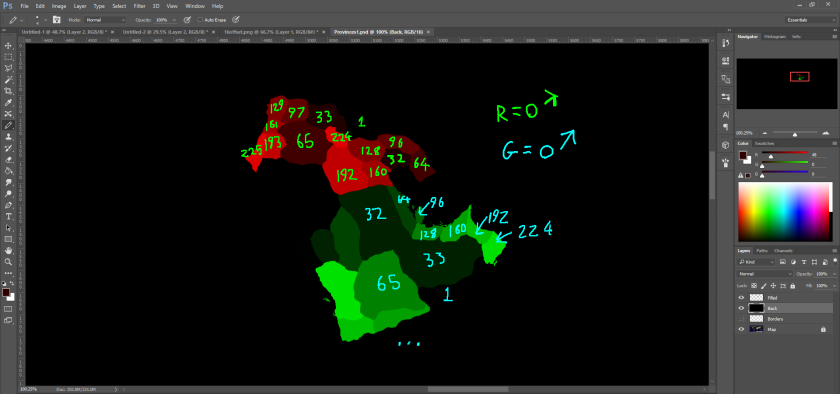
Thus: province 0 should be coloured (0, 0, 0). Province 1 should be (1, 0, 0). Province 255 should be (255, 0, 0).

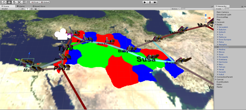
Above, you can see the source index-map I used to do this, and the result in Unity. Setting these colors is as simple as using mat.SetVector(“trueColors” + i, new Vector4(whateverColor)); in an external C# script, and giving it a reference to the Material with the province shader. You can’t imagine how happy I was when this worked (I was certain that what I wanted to do was impossible).
So, with that, I could easily have extended the system to use green and blue channels also, giving me 3 x 256 potential provinces, more than I’d ever need (and slightly less than EU4). But I wasn’t done here. I’d set out to make province-drawing easy. However, since each province increased its r value by only 1, and since it’s smart to put provinces 0, 1, 2 etc next to each other, the result is areas that are too similarly coloured to properly distinguish. It can be worked around with the purple outline, as seen above, but it takes more time.
EU4 doesn’t have to deal with this. Provinces are assigned a random color, and can be looked up in a database. As established earlier, I can’t do this. But I don’t really need unique combos of rgb: what I need is a sequence of numbers that aren’t close together to be decodes such that they are close together. Enter the Offset series.
The Offset Series: Swapping Your First and Second Digit
After much pen-chewing, a solution did dawn on me. It was conceivable, even to my poorly-math’d-up brain, to shift all digits in the series of numbers (the series, as in 0, 1, 2, 3 …) into a series of numbers that were, say, 10 digits apart, and back again. It’s a bit like turning a 2D array into a 1D array.
Say we have the series (1, 2, 3 …). This is our indices of provinces in its normal order. Accessing it by an identical red value means that I have to draw my map using that series, as seen above. Now, a conceivable alternative might be:
Normal Series: 1, 2, 3 … 11, 12, 13 … 21, 22, 23OffsetSeries: 10, 20, 30 … 11, 21, 32 … 12, 22, 32The first 10 values in the normal series (n-series) become the first values in each division-of-10 up to 99, in the new offset series (0-series). The second set of values – the elevens-and-teens – become the second values in each division of 10. Essentially, this is just swapping the digits around. But it works fine with divisions of not-10 as well.
If you can convert between these two series at will, you can take some well-spaced r-colours on an image file, and correctly use them to access an array in the right order. Province 1 can be represented by r = 10. Province 2 by r = 20. Province 12 by r = 21.
How do you convert between the n-series and o-series?
Where r is the red value in an image, and i is the index of the province we want it to represent:
[What order-of-10s is this o-series number in? Is it in the 20s? The 30s? 30 / 10 = 3, so this becomes the new single-unit.]
i = (r – r % 10) / 10 + …
[What’s the difference between this o-series number and the next multiple of 10? In other words, does it end in 2, 3, 4 … ? Multiply this by 10 as a fraction of the limit you want to stop at.)
… (r % 10) * (100 / 10)
More genrally:
The Offset Function
i = (r – r % m) / m + (r % m) * (l / m)
Where i is the index, r is the value (red), m is the multiple of offset (do you want to offset by 10? 16? 128?), and l is the max number before the sequence loops back and starts sorting the next order of numbers.
Magically, this equation works backwards, too. To get the o-sequence from the n-sequence, simply make r = n and i = 0.
Implementing this into the shader. Note that I went with an offset multiple of 32, allowing 8 offset steps before a reset to a similair colour. It’s uncommon for provinces to border more than 8 other provinces:
fixed4 frag (v2f i) : SV_Target
 {
    // What colour is this pixel in the index-map image?
    fixed4 col = tex2D(_MainTex, i.uv);

   // Take the value (r for red, but it could be red, blue, or green)       that's being used for indexing.
    int r = (col[0] + col[1] + col[2]) * 255;

   // Clamp b and g channels to 1 and 2, respectively. Use that to  increase the sequence by 256.
    // Note that these numbers should never both be above 0. This is just an algorithmic "or" statement that makes an assumption
    // about how the index-image is being drawn.
    int c = clamp(col[1] * 255, 0, 1) + (clamp(col[2] * 255, 0, 1) * 2);

    // Convert from offset-series to normal-series, add the 256 offset.
    int index = (r - (r % 32)) / 32 + (r % 32) * (256 / 32) + c * 256;

    // Access the array.
    fixed4 newCol = myArray[index];

    // Return the true colour.
    return newCol;
 }
This allows me to define provinces with much greater ease:

Shader Source Code:
Shader "Unlit/ProvinceTest"
{
  // This shader colors provinces according to their index color, into their true color. It should be paired with a C# script,
  // editing its array of true colours via Material.SetVector("myArray" + number, Color);
  // It was adapted from an example shader, and there are some elements that may no longer serve a purpose.

  Properties
  {
    _MainTex ("Texture", 2D) = "white"

  SubShader
  {
    Tags{ "Queue" = "Geometry" "RenderType" = "Opaque" }
    //Tags{ "Queue" = "Transparent" "IgnoreProjector" = "True" "RenderType" = "Transparent" }
    ZWrite Off
    Blend SrcAlpha OneMinusSrcAlpha
    LOD 100

    Pass
    {
    CGPROGRAM
    #pragma vertex vert
    #pragma fragment frag
    // make fog work
    //#pragma multi_compile_fog

    #include "UnityCG.cginc"

    uniform float4 myArray[767];

    struct appdata
    {
    float4 vertex : POSITION;
    float2 uv : TEXCOORD0;
    float4 color : COLOR;
    };

    struct v2f
    {
    float2 uv : TEXCOORD0;
    //UNITY_FOG_COORDS(1)
    float4 vertex : SV_POSITION;
    //float4 color : COLOR;
    };

    sampler2D _MainTex;
    float4 _MainTex_ST;

    sampler2D _IndexTex;
    float _Coord;

    // Unsure of what this does.
    v2f vert (appdata v)
    {
    v2f o;
    o.vertex = mul(UNITY_MATRIX_MVP, v.vertex);
    o.uv = TRANSFORM_TEX(v.uv, _MainTex);
    return o;
    }

    fixed4 frag (v2f i) : SV_Target
    {
      // What colour is this pixel in the index-map image?
      fixed4 col = tex2D(_MainTex, i.uv);

      // Take the value (r for red, but it could be red, blue, or green) that's being used for indexing.
      int r = (col[0] + col[1] + col[2]) * 255;

      // Clamp b and g channels to 1 and 2, respectively. Use that to increase the sequence by 256.
      // Note that these numbers should never both be above 0. This is just an algorithmic "or" statement that makes an assumption
      // about how the index-image is being drawn.
      int c = clamp(col[1] * 255, 0, 1) + (clamp(col[2] * 255, 0, 1) * 2);

      // Convert from offset-series to normal-series, add the 256 offset.
      int index = (r - (r % 32)) / 32 + (r % 32) * (256 / 32) + c * 256;

      // Access the array.
      fixed4 newCol = myArray[index];

      // Return the true colour.
      return newCol;
        }
      ENDCG
    }
  }
}

